What Are the Top Types of Printed Board?
Choosing the right Printed Board is rarely a simple matter of counting layers. Designers must balance electrical performance, mechanical movement, heat, cost, and production volume. A single-sided board may suit a basic control panel, while a multilayer board supports dense routing inside a smartphone. The difference is visible in the factory. Copper traces become finer. Drilling becomes more demanding. Errors become expensive.
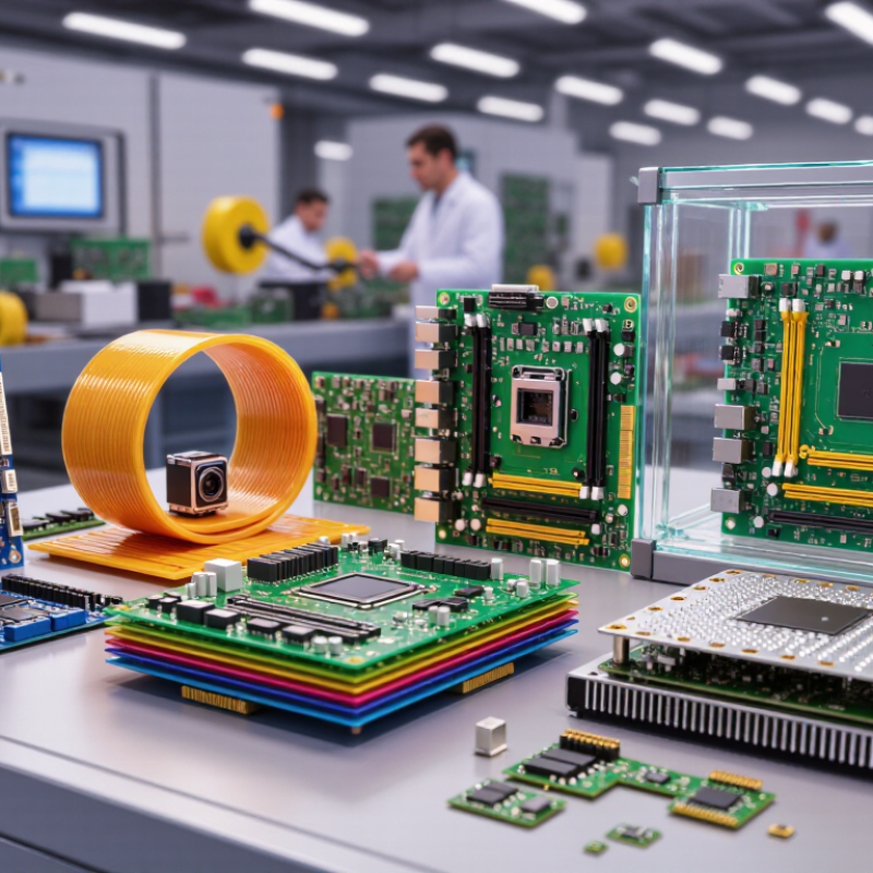
Industry expert E. Jan Vardaman has stated, “Packaging is becoming the system.” That observation helps explain why Printed Board selection now involves more than substrate choice. Rigid boards offer stability for computers and industrial equipment. Flexible boards bend through cameras, medical sensors, and wearable devices. Rigid-flex designs combine both advantages, but their engineering and inspection requirements are higher. HDI boards create compact connections through microvias and fine-line structures. Metal-core boards move heat away from powerful LEDs and other hot components.
The best type depends on the product’s real working conditions. Not the trendiest option. A low-cost board can fail when vibration, moisture, or heat was underestimated. I have seen specifications focus heavily on size while overlooking repair access and thermal paths. That is a useful warning. Technical comparisons should examine layer count, dielectric material, copper weight, surface finish, impedance control, and compliance documentation. Manufacturing capability matters just as much. A design that looks excellent on paper may become unreliable during mass production. This guide explores the top Printed Board types and the practical reasons each one earns its place. Some choices remain imperfect. That is normal. Good engineering makes those compromises visible.
What Is a Printed Board and How Is It Classified?
A printed board is an insulated panel that mechanically supports electronic components and connects them through conductive copper paths. It is commonly called a printed circuit board, or PCB. Its classification begins with structure: single-sided boards use copper on one surface, double-sided boards use both surfaces, and multilayer boards contain several copper layers separated by dielectric material.
Boards are also classified by flexibility and manufacturing purpose. Rigid boards suit computers, appliances, and industrial controllers. Flexible boards bend around hinges, cameras, and compact displays. Rigid-flex boards combine both properties, but their design demands tighter mechanical control. High-density interconnect boards use microvias and fine traces for smaller products. Metal-core boards improve heat removal, especially in power and lighting equipment. IPC’s World PCB Production Report indicates that Asia produces more than four-fifths of global PCB output, showing how important regional manufacturing capability remains. A 2024 market report estimated the global PCB market at about 90 billion dollars in 2023. These figures are useful, though market estimates can differ.
Tips: Classify a board by its layer count, material, flexibility, and application. Do not rely on appearance alone. Check the fabrication drawing, copper thickness, dielectric stack-up, and operating temperature. The boundary is not always tidy. A board may be rigid, multilayer, high-density, and metal-backed at the same time. In my design reviews, confusing “double-sided” with “two-layer” has caused avoidable specification errors. The terms sound similar. They are not always interchangeable.
What Are the Top Types of Printed Board? - What Is a Printed Board and How Is It Classified?
| Printed Board Type | Defining Structure | Typical Layer Configuration | Common Materials | Common Applications | Main Benefits | Typical Limitations |
|---|---|---|---|---|---|---|
| Single-Sided PCB | Conductive copper pattern is present on one side of the insulating substrate. | One copper layer; component mounting is generally on the opposite or same side depending on the design. | Copper foil with a rigid or flexible dielectric substrate; common rigid substrates include paper-based phenolic and glass-fiber epoxy materials. | Simple controls, power supplies, consumer products, basic sensors and low-density electronics. | Lowest complexity, simple manufacturing process and generally low cost. | Limited routing area and lower circuit density; crossing conductors may require jumpers or other design compromises. |
| Double-Sided PCB | Copper patterns are formed on both sides of the insulating substrate. | Two copper layers, commonly interconnected with plated through-holes or vias. | Glass-fiber epoxy laminate, copper foil, solder mask and protective surface finish. | Industrial controls, automotive modules, instrumentation, communications equipment and general electronic assemblies. | More routing space and component density than a single-sided board while remaining relatively straightforward to manufacture. | Less routing capacity than multilayer boards and may require careful signal, power and thermal planning. |
| Multilayer PCB | Three or more copper layers are separated by dielectric layers and bonded into one board. | Usually four or more copper layers, with signal, power and ground layers arranged according to electrical and mechanical requirements. | Glass-fiber epoxy laminates and prepreg, copper foil, solder mask and plated interconnections. | Computing systems, networking equipment, medical electronics, industrial equipment and complex embedded systems. | High wiring density, improved power distribution, controlled impedance options and better electromagnetic compatibility when properly designed. | Higher fabrication cost, longer production time and greater sensitivity to stack-up, drilling, registration and thermal issues. |
| Rigid PCB | A non-flexible board that maintains its shape during installation and operation. | Can be single-sided, double-sided or multilayer. | Rigid laminates such as glass-fiber epoxy, with copper conductors and protective solder mask. | Computers, control panels, appliances, industrial equipment and fixed electronic modules. | Mechanical stability, predictable dimensional control and broad compatibility with automated assembly. | Cannot be repeatedly bent and may require connectors or additional wiring where the assembly must move. |
| Flexible PCB | Uses a bendable dielectric film so the circuit can flex or conform to a three-dimensional shape. | Available as single-layer, double-layer or multilayer flexible circuits. | Polyimide or similar flexible films, rolled or electrodeposited copper, flexible coverlay and stiffeners where required. | Wearable devices, cameras, displays, compact electronics, movable assemblies and space-constrained products. | Reduces wiring and connector count, saves space and weight, and supports bending or dynamic movement when correctly designed. | Material and assembly costs can be higher; bend radius, flex-cycle life, handling and component support require careful control. |
| Rigid-Flex PCB | Combines rigid board sections with permanently bonded flexible circuit sections. | Mixed rigid and flexible layer stack-up; the exact construction depends on the required electrical and mechanical zones. | Rigid laminates combined with polyimide-based flexible layers, copper and flexible coverlay. | Aerospace systems, medical instruments, compact devices, cameras and equipment with constrained interconnections. | Integrates interconnects into the board, saves assembly space and can improve reliability by reducing separate connectors. | More complex design, fabrication and inspection requirements than conventional rigid or flexible boards. |
| Metal-Core PCB | Uses a metal base, commonly aluminum or copper, to conduct heat away from heat-generating components. | Often a single copper circuit layer separated from the metal base by a thermally conductive dielectric; multilayer constructions are also possible. | Aluminum or copper base, thermally conductive dielectric, copper circuit layer and protective finish. | LED lighting, motor drives, power conversion and other applications with significant thermal loads. | Improves heat spreading and can reduce the need for separate heat-management hardware. | Less suitable for some high-density routing designs; fabrication, isolation and mechanical processing require specialized considerations. |
| HDI PCB | High-density interconnect construction uses fine traces, small capture pads and microvias, including blind or buried vias in suitable designs. | Usually implemented as a multilayer structure; layer count varies with routing density and component technology. | High-performance laminates, copper foil, dielectric build-up materials and laser-drilled or mechanically drilled interconnections. | Smart devices, compact computing products, high-density modules and advanced communication equipment. | Supports smaller packages, shorter interconnects, compact form factors and increased routing density. | Requires tighter manufacturing tolerances, advanced process control, specialized inspection and higher production cost. |
Classification note: Printed boards are commonly classified by the number of conductive layers, mechanical form, substrate construction, thermal-management method and interconnection technology. A single board may belong to more than one category, such as a rigid multilayer board or a flexible HDI board.
Related Posts
-
What Are the Top Types of Circuit Boards for Buyers?
-

How to Choose a Prototype Circuit Board in 2026?
-

How to Maximize Efficiency with Rigid Flex Boards in Your Projects
-

Global Leaders in PCB Assembly: Unlocking Top Quality and Efficiency for Worldwide Exports
-

Understanding Industry Production Standards for Best Circuit Board Assembly Techniques
-
Mastering the Art of Best Printed Circuit Board Assembly Step by Step Guide

 Phone
Phone WhatsApp
 Email
Email
Offer Electronics Manufacturing All-in-One
PCBONLINE® is a registered trademark or service mark of pcb online limited or its affiliates.
Copyright © 2001-2024 Pcb Online Limited. All rights reserved