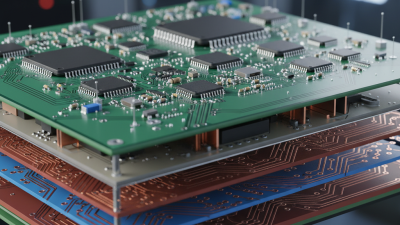
Choosing a Circuit Board is not a simple matter of comparing prices. The board must match the product’s heat, space, signal, and production requirements. A rigid multilayer board may suit a control cabinet, while a flexible board can move inside a wearable device. Rigid-flex designs add reliability where repeated bending and limited space meet. HDI boards support dense smartphones and compact medical equipment. Metal-core boards help move heat away from high-power LEDs.
Market data confirms the sector’s scale, although estimates differ. Grand View Research valued the global printed circuit board market at about US$89.7 billion in 2023. Fortune Business Insights reported a lower estimate for the same year. Different definitions and research methods explain part of the gap. That difference deserves attention. Buyers should not treat one forecast as absolute truth. IPC industry reports also continue to track supply pressure, factory utilization, and electronics demand across major regions.
PCB industry analyst Dr. Hayao Nakahara has described the printed circuit board as “the backbone of the electronics industry.” His statement remains practical. A board is not merely a green panel with copper traces. It determines assembly efficiency, repair access, thermal behavior, and long-term product stability. Experienced buyers inspect layer count, copper weight, dielectric materials, impedance control, certification, and supplier process records. They also examine samples under real operating conditions. A low quotation can become expensive after failures appear. The sections ahead compare the top Circuit Board types, their strengths, limitations, and best-fit applications. No single type wins every project. That is where selection becomes more thoughtful—and sometimes more difficult.
A circuit board is not merely a flat sheet with copper lines. It is a controlled platform that connects, supports, and powers electronic components. Its structure usually includes a substrate, conductive copper layers, solderable pads, drilled holes, and a protective surface coating. Multilayer boards also contain internal copper planes. These planes can carry power or reduce electrical noise.
The board’s function depends on its layout. Traces guide signals between components, while thermal areas help move heat away from sensitive parts. A careful inspection should check layer count, material strength, hole quality, spacing, and solder mask coverage. Small defects can create large failures. That is easy to underestimate.
The main categories include single-sided, double-sided, and multilayer circuit boards. Single-sided boards suit simple controls and low-density devices. Double-sided boards provide more routing space without excessive thickness.
Multilayer boards support compact, high-speed products with complex power systems. Flexible boards bend inside hinges, cameras, and narrow assemblies. Rigid-flex designs combine fixed support with controlled movement.
Buyers should match the board type to voltage, signal speed, heat, space, and expected service life. A basic board may look cheaper, yet it can require more assembly space and wiring. Multilayer construction costs more, but it may improve reliability and reduce product size. In practice, the cheapest option is not always the most economical. Thermal testing and prototype review can expose weaknesses before volume production. I would also question any specification that lacks material details, tolerance limits, and inspection records.
When buyers compare circuit boards, the layer count should match the product’s electrical and mechanical needs. Single-sided boards place copper traces on one surface. They suit simple controls, low-density circuits, and cost-sensitive devices. Their layout is easier to inspect and repair. However, crossing traces may require wire links or a larger board. That extra space can affect the enclosure design.
Double-sided boards carry copper on both surfaces, connected through plated holes. This arrangement supports tighter layouts and more components. It often improves routing flexibility without greatly increasing board thickness. Multilayer boards add internal copper layers between insulating materials. They handle dense processors, controlled impedance, power distribution, and complex signal paths. A four-layer design can also provide a continuous ground plane, reducing noise and improving signal stability. More layers are not automatically better. They increase fabrication cost, inspection demands, and repair difficulty.
Tips: Ask for the expected current, signal speed, component count, and available space before selecting a structure. Check the manufacturer’s minimum trace width, hole size, and layer alignment limits. Leave thermal paths around power components. A rushed layout may pass a basic test but fail during heat cycling. It is easy to over-specify a board. Sometimes, a carefully routed double-sided design performs better financially than a small multilayer board. The perfect choice is not always obvious. Review prototypes under real temperature, vibration, and load conditions before approving production.
Choosing among rigid, flexible, and rigid-flex boards starts with movement, space, and assembly conditions.
Rigid boards use fiberglass-based laminates and provide stable platforms for connectors, processors, and power circuits. They suit equipment with flat enclosures, predictable mounting points, and moderate thermal demands. Their tooling is familiar, and automated assembly is usually straightforward. That predictability helps buyers compare quotes accurately. Still, rigidity can force extra connectors or wiring.
Flexible boards use thin polymer films that bend around corners and through narrow gaps. They can reduce cable weight, connector count, and assembly time. However, the bend radius matters greatly. A flex tail folded too tightly may crack its copper traces after repeated movement. Buyers should request bend-cycle data, material details, and a drawing showing the neutral axis. Dynamic applications need different construction from a flex section bent only during assembly. It sounds obvious, but it is often missed.
Rigid-flex boards combine stable component areas with flexible interconnects. They can remove separate cable harnesses and free valuable enclosure space. This design may improve reliability, but fabrication and inspection are more demanding. A sound quotation should identify layer count, controlled impedance, surface finish, tolerances, and test coverage. Ask how the supplier checks plated holes, bend zones, and solder-mask registration. I have found that a beautiful layout can fail when the bend path meets a stiffener edge. Reviewing the mechanical model early prevents expensive revisions. Not every compact design needs rigid-flex. Sometimes, a rigid board and replaceable cable remain easier to service. That trade-off deserves honest engineering review.
Buyers choosing circuit boards for demanding systems should match the board to its electrical and thermal environment. High-speed designs often use HDI or multilayer boards with controlled impedance, low-loss dielectrics, and carefully planned return paths. Back-drilled vias can reduce signal reflections in dense channels. Small details matter. A misplaced via can weaken an otherwise excellent layout.
High-frequency applications need materials with stable dielectric constants and low dissipation factors. Surface copper roughness also affects insertion loss as frequencies rise. For radar, wireless, and testing equipment, engineers should review data above the target operating frequency. A board passing basic continuity checks may still perform poorly at speed. That is an uncomfortable point, but it deserves attention. A 2024 global PCB market report projects the industry to grow from about 95 billion dollars in 2024 to more than 145 billion dollars by 2032. IPC industry reports also continue to identify high-density interconnect and advanced materials as important technology priorities.
Tips: Ask for impedance coupons, thermal-cycle results, material certificates, and cross-section images. For heavy-duty equipment, consider heavy-copper boards, metal-core construction, or reinforced multilayers. Copper thickness around 3 to 6 ounces can support higher current, but it may complicate etching and fine-pitch assembly. The right choice is rarely the thickest board. Reliability depends on heat paths, connector strength, moisture protection, and realistic vibration testing. Allow design margin. Real equipment is less predictable than the laboratory.
Choosing a circuit board starts with the application, not the lowest quotation. A simple two-layer rigid PCB may suit a sensor or control panel. High-density interconnect boards fit compact products with fine-pitch components. Flexible and rigid-flex boards handle repeated bending, tight packaging, or moving connections. Metal-core boards help remove heat from high-power lighting and power electronics. The best type depends on electrical, mechanical, and thermal demands.
Industry data shows why this decision matters. Fortune Business Insights estimated the global PCB market at about USD 89.7 billion in 2023. Its report projects continued growth through 2032, driven by automotive electronics, communication equipment, and industrial systems. Buyers should compare layer count, dielectric material, copper thickness, impedance control, and expected operating temperature. IPC-2221 provides useful design guidance, but it does not replace application-specific testing. Standards guide decisions.
Cost comparisons need more depth. Ask for stack-up drawings, material data sheets, microsection results, and test records. Check solderability, hole reliability, surface finish, and lead-time stability. A low unit price can still be a poor choice. I have seen sourcing teams overlook assembly yield and redesign costs. That mistake is expensive. For flexible boards, inspect bend radius and dynamic-cycle data. For high-speed designs, review insertion loss and signal integrity reports. Buyers should also examine supplier process controls and change-notification procedures. Some comparisons remain uncertain until prototypes face vibration, humidity, heat, and repeated power cycles.
WhatsAppOffer Electronics Manufacturing All-in-One
PCBONLINE® is a registered trademark or service mark of pcb online limited or its affiliates.
Copyright © 2001-2024 Pcb Online Limited. All rights reserved