Choosing a traffic VMS LED display is not just a matter of picking a large, bright screen. Drivers may have only a few seconds to read a message, sometimes in rain, glare, or heavy traffic. That makes legibility, placement, and dependable operation essential. Small details matter. Viewing distance affects the character size and pixel pitch that will work well. Brightness must remain readable in daylight without becoming uncomfortable at night. More is not always better.
The seven tips in this guide focus on practical decisions: matching display size to the road, checking visibility from real approach angles, assessing weather protection, and reviewing power use and control options. They also cover message flexibility, maintenance access, and the supplier’s technical support. Ask for specifications, installation guidance, and clear service terms, then compare them against the conditions at your site. A sample message viewed from a parking lot may look crisp; the same text can be harder to read from a moving vehicle. That gap is easy to underestimate. No single display suits every road, and even a careful checklist cannot replace site-specific assessment. Use these tips to ask better questions and identify trade-offs before purchase. The right choice should help operators share timely information while giving drivers a clear, readable message.
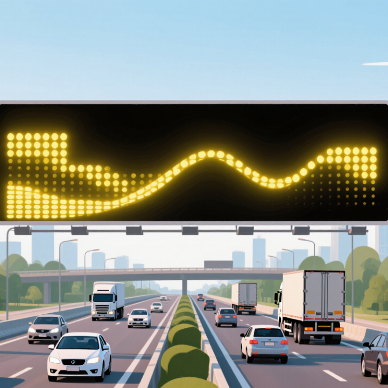
A traffic VMS should be sized around the message drivers must read, not the largest screen available. The FHWA’s 11th Edition MUTCD guidance uses a practical limit of three lines and about 20 characters per line for changeable message signs. That gives roughly 60 character positions per phase.
It is a ceiling, not a target.
Spaces, abbreviations, and line breaks consume room quickly. For example, “RIGHT LANE CLOSED 1 MILE” is easier to scan when split into short, meaningful lines than squeezed into one row. Keep each phase focused on one action or condition.
NCHRP Report 600, Human Factors Guidelines for Road Systems, stresses that roadway information must fit drivers’ attention and decision demands. In practice, that means testing the message at realistic viewing distances and speeds—not just checking it on a laptop. Small detail. Big difference.
When specifying the LED display, confirm its character height, viewing distance, and supported line layout can present the intended message clearly. A display that technically fits 60 characters may still make them hard to read in rain, glare, or nighttime conditions.
I’d leave spare capacity for clarity; it can feel wasteful on paper. Check applicable local requirements, too, since agencies may set stricter rules or operational formats than the MUTCD guidance.
The 1-inch-per-30-foot rule is a useful starting point: each inch of letter height offers roughly 30 feet of viewing distance. An 18-inch character, for example, suggests about 540 feet. But that estimate assumes clear sightlines, strong contrast, and enough time to read. Real roads are less tidy. Rain, glare, vibration, and a sign viewed from an angle can all reduce legibility.
The Federal Highway Administration’s 2023 Manual on Uniform Traffic Control Devices specifies minimum changeable-message-sign character heights of 18 inches for freeway applications and 12 inches for other applications. These figures offer a practical check against the rule: 12-inch letters imply about 360 feet, while 18-inch letters imply 540 feet. Treat those distances as planning estimates, not promises. At 55 mph, a vehicle travels about 242 feet in three seconds, leaving little time for a long message. Keep the wording brief, and test it from an approaching vehicle, not only from the control room. Small text fails. I still find the rule easy to overtrust; a clean layout can look readable up close and blur at speed. Include viewing distance, letter height, and road conditions in field checks.
A traffic VMS must remain legible where drivers actually see it, not just from directly in front. EN 12966 luminance classes help specify sign brightness for different viewing conditions. Choose a class that suits ambient light, including bright midday sun, rather than relying on a headline brightness figure. At night, excessive luminance can also reduce comfort and readability.
Beam-width classes describe how light is distributed across viewing angles. Match the declared horizontal and vertical coverage to the road layout, mounting height, and likely approach paths. A sign over a straight lane has different needs from one positioned before a bend. Small angles matter. Check the evidence. Ask for test documentation showing the stated EN 12966 classes, and compare those results with the installation geometry. A broad beam is not automatically better if it sends light where drivers do not need it.
Specifications can look precise while overlooking a roadside tree, a curve, or a high-mounted sign. Walk the approach at driver eye level, where practical, and consider both daytime and night-time views. I would revisit the selection if the available drawings do not show viewing angles clearly. The drawing may be wrong. Pair the luminance and beam-width classes with checks for contrast, character size, and environmental conditions, then confirm visibility after installation.
A traffic VMS LED display must do more than look bright in a showroom. Check its documentation against the applicable edition of NEMA TS 4 and the project specification. Confirm that the tested configuration matches the equipment being offered, including the sign housing, modules, power supplies, and control components. A certificate for one assembly may not cover a modified cabinet. Small detail, big difference.
Review the environmental and structural requirements that apply to the installation. Ask for test records covering temperature, moisture, wind loading, and vibration, rather than relying on broad claims such as “all-weather.” Check enclosure seams, cable entries, door latches, and drainage paths; these are easy places for water or dust to become a problem. Inspect the electrical documentation too, including grounding, overcurrent protection, and power behavior during startup. Keep the evidence tied to the exact model and configuration.
Field access matters. Can a technician replace a module safely from the rear, and are service clearances shown on the drawings? A tidy datasheet can still leave practical questions unanswered. I would not treat a standards checklist as proof of long-term reliability; installation quality and maintenance affect performance too. Ask the supplier to clarify gaps in writing, then compare the response with the project’s acceptance requirements.
| Tip | Hardware or design area | What to verify | Useful evidence | Project acceptance check |
|---|---|---|---|---|
| 1. Confirm the applicable standard edition | NEMA TS 4 compliance | Identify the NEMA TS 4 edition named in the contract or procurement documents. Check that the proposed sign hardware and its documented configuration are evaluated against that edition and the project requirements. | Compliance matrix, equipment documentation, and relevant test reports that identify the standard edition and equipment covered. | Confirm that the sign configuration, options, and test documentation match the approved submittal; do not treat an unspecified claim of “TS 4 compliant” as sufficient evidence. |
| 2. Check the display matrix and message layout | LED modules, pixels, and character presentation | Verify the specified sign dimensions, pixel matrix, character size, and available text lines against the required messages and viewing conditions. There is no single pixel pitch or matrix that suits every roadway installation. | Dimensioned drawings, pixel-matrix details, sample messages, and legibility or visibility analysis based on the project’s viewing distance and speed assumptions. | Confirm that required messages fit the approved display area and remain legible under the project’s stated operating conditions. |
| 3. Evaluate visibility in real operating conditions | LED output, dimming, and optical performance | Review documented daytime and nighttime performance, automatic or controlled brightness adjustment, and any measures intended to limit glare. Check that the control approach suits the site’s ambient-light conditions. | Manufacturer’s photometric data, dimming-control description, and test results for the proposed display configuration. | Compare documented performance with the values and operating requirements specified for the project; verify dimming operation during acceptance testing. |
| 4. Match environmental protection to the site | Enclosure, seals, ventilation, and corrosion protection | Assess exposure to rain, dust, temperature extremes, condensation, salt, and other site conditions. Verify that enclosure and thermal-management provisions are documented for the installed configuration. | Enclosure drawings, environmental test documentation, materials and finish information, and the stated operating-temperature range. | Check that the proposed environmental capabilities meet the contract and site design conditions; verify access panels, seals, and cooling components during inspection. |
| 5. Verify electrical and surge-protection details | Power distribution, grounding, and protection | Review input power requirements, circuit protection, grounding and bonding provisions, and surge-protection arrangements. Confirm compatibility with the site’s electrical supply and the approved wiring design. | Electrical schematics, load information, grounding details, and documentation for protective devices. | Confirm that installation and test records follow the project electrical requirements and applicable codes; verify protective components are present and correctly connected. |
| 6. Inspect structure, mounting, and service access | Sign cabinet, supports, fasteners, and maintainability | Check that cabinet and mounting details are coordinated with the structural design, site loads, and installation drawings. Review safe access to serviceable components and the method for replacing modules or parts. | Approved structural calculations, mounting drawings, cabinet drawings, and maintenance-access documentation. | Verify that the installed sign matches the approved design and that required clearances, attachment details, and maintenance access are available. |
| 7. Require a complete verification and maintenance plan | Factory testing, site commissioning, and diagnostics | Establish how display functions, message presentation, communications, brightness control, and fault reporting will be checked. Confirm that diagnostic features and replacement procedures are documented. | Factory and site test plans, commissioning records, diagnostic documentation, and maintenance instructions. | Close acceptance only after required tests pass, deficiencies are resolved, and operating and maintenance documents are delivered. |
When comparing traffic VMS LED displays, rated power gives a useful starting point for estimating electricity costs. Check whether the figure applies to typical operation or maximum brightness. A sunny roadside may demand more output than a shaded approach, while nighttime dimming can reduce consumption. Small details matter.
For a simple comparison, multiply rated kilowatts by expected operating hours and your local electricity rate. Then ask suppliers for power figures at realistic brightness settings, not just peak output. Include standby use and control equipment where applicable. A common spreadsheet mistake is treating every hour as full-brightness operation. That matters. Actual traffic, weather, and dimming schedules can make the estimate imperfect.
L70 life describes the estimated time until LEDs produce 70 percent of their initial light output under specified test conditions. It does not mean the display suddenly stops working. Compare L70 figures alongside rated power, warranty terms, and the cost of access equipment and service visits. A longer L70 may reduce replacement pressure, but only if the test conditions match your intended use. Look closely at the assumptions. They are easy to overlook. Ask for the measurement method and plan for gradual brightness loss; I would not treat one headline number as a guarantee.
Compare Rated Power and L70 Life for Long-Term Operating Costs
Planning scenarios only—not product specifications. Annual electricity cost is calculated as rated power × 12 operating hours per day × 365 days × $0.15 per kWh. L70 is the hours until output reaches 70% of its initial level; confirm the rated L70 value and test conditions in each supplier’s datasheet. Actual costs depend on operating schedules, electricity rates, brightness settings, and maintenance.
WhatsAppOffer Electronics Manufacturing All-in-One
PCBONLINE® is a registered trademark or service mark of pcb online limited or its affiliates.
Copyright © 2001-2024 Pcb Online Limited. All rights reserved